
Recently, VMware introduced the Express Storage Architecture (ESA) to the newly released vSAN 8. Replacing the “disk groups” in the original storage architecture (OSA) with “storage pools,” ESA eliminates the need for dedicated SSDs to act as cache accelerators. This remarkable change, to some extent, avoids issues such as low utilization of dedicated cache disks and the high likelihood of cache breakdown in versions prior to 8.0.
It should be noted, however, that prior to the vSAN update, SmartX was able to avoid the aforementioned issues by optimizing its distributed storage caching mechanism. This is accomplished through the use of a unified cache space and intelligent hot and cold data management.
In this article, we will compare the caching mechanisms of vSAN (using vSAN 7 as an example) and SmartX distributed block storage component ZBS*. Following that, a comparison of VM performance based on these two caching mechanisms is performed to disclose their business impacts.
* ZBS is a built-in component of SMTX OS (SmartX HCI software). It can be delivered in a hyper-converged form together with SmartX native virtualization ELF.
Summary
- vSAN 7 divides cache space into two parts: a write buffer (30% capacity) and a read cache (70% capacity). When too much data is accessed, this caching mechanism can cause issues such as low cache utilization and cache breakdown, resulting in performance degradation.
- In ZBS, data is managed by a two-level LRU (Least Recently Used) algorithm and stored in the unified cache space. This mechanism helps avoid VM performance degradation due to traffic surges while fully utilizing cache capacity.
- Based on the same hardware configuration and I/O read/write scenarios, we compared the VM performance with different caching mechanisms by writing 300 GB of data to VMware HCI (vSphere & vSAN) and 500 GB of data to SMTX OS (ELF & ZBS). The results showed that vSAN suffers from a I/O performance decrease caused by cache breakdown. In contrast, even with more writes, SMTX OS didn’t experience cache breakdown, ensuring stable support for VMs.
Concerns over Caching Mechanism
Compared with all-flash configurations, hybrid configurations are more common in HCI or distributed storage implementation. In a hybrid configuration, both SSDs and HDDs are used, with SSDs serving as the cache layer and HDDs serving as the capacity layer. A distributed storage pool built this way can automatically identify hot and cold data via algorithms, leading to the improvement in performance, utilization and cost-effectiveness.
Some HCI products with hybrid configurations divide cache capacity into individual read and write spaces. vSAN 7 and previous versions, for example, divide cache disks in each disk group into write buffers (30%) and read caches (70%), based on their capacity share. If data reads miss cache or write buffers are full, reads and writes will directly take place at the capacity layer1.
While this solution safeguards space isolation for read and write I/O against cache breakdown, it also results in under-utilization of high-speed storage medium cache space. For example, if the guest VMs write more and read less, the write space is likely to be full while plenty of read space remains unused, and vice versa.
This is a typical working scenario for healthcare integration platforms. An integration platform usually serves to assist the hospital in making intelligent decisions from an integration of enormous data. It extracts data from hospital system databases (for example, HIS, EMR, and LIS) and performs data transformation and loading via ETL. This process occurs in the intermediate database to reduce the workloads in the production database.
As a large volume of data writes to the intermediate database, the cache space is prone to filling up. If the cache space is separated as read and write in a fixed ratio, it is very likely that the amount of writes exceeds writing cache capacity. In this way, the cache breakdown and business performance degradation are easily foreseen.
To address this problem, ZBS uses a unified cache space where the whole capacity is used for both reading and writing data. This prevents the cache space from running out and affecting storage performance.
Moreover, ZBS also leverages the hot and cold data tiering to store data depending on the access frequency. That is, hot data that is frequently read and written is stored in SSDs while cold data without frequent reads and writes is stored in HDDs. This algorithm further improves cache layer utilization and ensures the stable performance of business systems.
We will elaborate VMware and SmartX’s distributed storage caching mechanisms in the following section.
Caching Mechanisms
vSAN
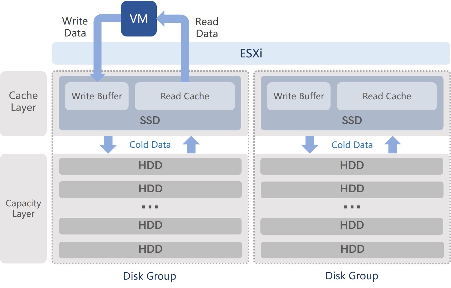
vSAN 7 uses Disk Groups to group high-performance storage media (e.g., NVMe/SATA SSDs) and lower-performance storage media (e.g., SATA/SAS HDDs) into logical vSAN Datastore.
Each ESXi host can have 5 disk groups, with each disk group supporting up to 1 high-performance storage medium and 1-7 low-performance storage media. In hybrid configuration, High-performance storage medium is used as the cache layer where the entire capacity is divided into dedicated space for reads and writes at a ratio of 7:3. Writes from VMs will go to the cache layer at first and will be acknowledged immediately. Low-performance storage media is used as the capacity layer to hold cold data destaged from the cache layer.
The data written to the write cache space will be destaged to the capacity layer based on Elevator Algorithm. So the cache layer can have sufficient capacity to support subsequent I/O requests. When cold data is subject to read access, it will be loaded into the read cache space.
In addition, vSAN’s cache data can only be used in its disk group. And there is no redundancy arrangement.
ZBS
ZBS requires at least two SSDs to serve as cache in hybrid configurations. It employs a two-level LRU (Least Recently Used) algorithm to identify, tier and manage hot and cold data.
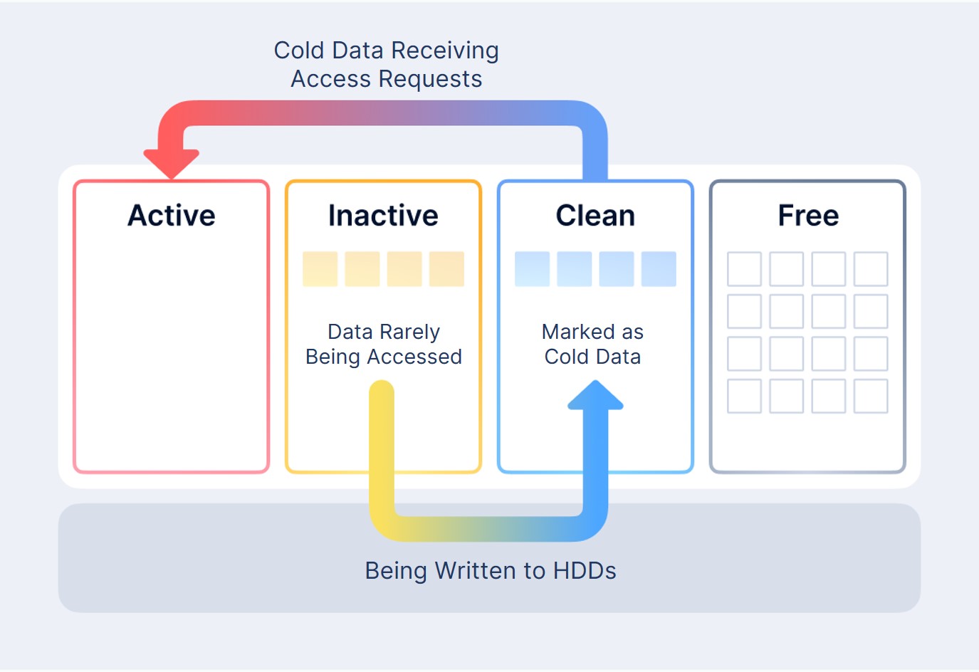
Generally, the LRU algorithm divides cache data into four groups: Active, Inactive, Clean and Free. Each group is allocated with an individual cache space.
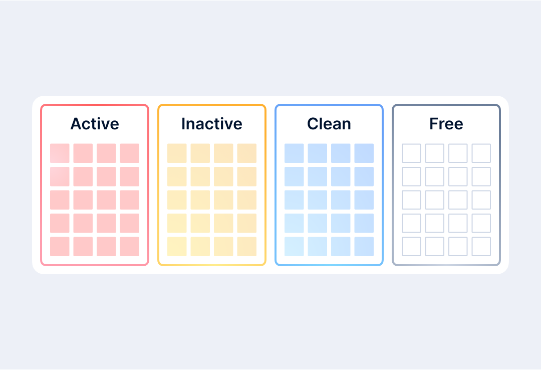
- Active caches the “hottest” data, which includes both the most frequently accessed data and data that transitions from cold to hot.
- Inactive caches the “second hottest” data, which includes first-written data and data that has not been accessed for a short period of time.
- Clean caches “cold” data which has completed HDD persistent storage and has not been accessed for a long time.
- Free is the free cache space that caches unused or reclaimed data.
How the Two-Level LRU Algorithm Works
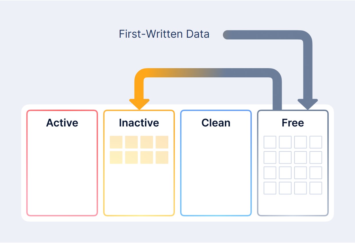
When the data is first written, a request for free data space is sent to Free as there is no record in cache. After the write is finished, the data will be moved to Inactive.
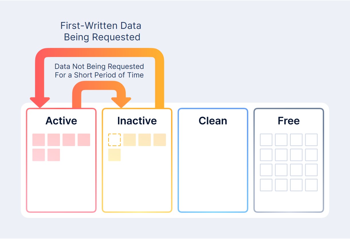
Active caches data blocks that have been accessed frequently. When the amount of data in Active exceeds the amount of data in Inactive, Active will rank data based on access frequency and move rarely accessed data to Inactive. When Active and Inactive have the same cache capacity, the transition will come to an end.
If the data in Active and Inactive takes up more than 20% cache capacity, a persistent disk storage operation will be triggered in Inactive. Earlier cached data in Inactive will be written to HDDs and marked as Clean in the cache layer. At this point, Clean data has copies in both HDDs and cache. If Clean data receives access requests afterwards, they will be re-marked as Active. Otherwise the data will be reclaimed and make room for new writes.
Caching Mechanisms for Data Read and Write Scenarios
Data Write Scenarios
- Cache Hits
a.Write data to cache space and tier data as hot and cold. - Cache Misses
a.If the cache is not full, data will be written to the free space in cache.
b.If the cache is full, data will be written to the capacity layer.
Data Read Scenarios
- Cache Hits
Upon receiving read requests, the system will use metadata to search for hits for the requested data, with priority given to the local node cache. If the data is found in the cache (Active, Inactive, and Clean), it will be read directly from the cache. - Cache Misses
a. If cache is not full
The system will query the local data (capacity layer) for the requested data. If the data exists, it will request data copies from the local capacity layer. Rather than directly reading data on the capacity layer, requesting data copies from the local capacity layer takes place by first querying the local cache to see if there is spare space. If there is sufficient cache space, the requested data copies will first be loaded from the local capacity layer into cache. And then data reads will be done through cache. Data is thus returned and read successfully.
b. If cache is full
Upon receiving read requests, if the system finds that the requested data has no copies in the local cache, and at that time, there is no more spare room in the local cache space, copies of the requested data will be read directly from the capacity layer.
Test, Validation & Comparison
Testing Environment
Hardware
We used the same hardware devices with the same configuration for each test. In particular, we used three Dell PowerEdge C6420 servers, with each configured as below:
| Parts | Model | Number |
| CPU | Intel(R) Xeon(R) Silver 4210R CPU @ 2.40GHz | 2 |
| MEM | 16GB DDR-4 | 8 |
| SSD | Intel D3-S4610 960GB | 2 |
| HDD | TOSHIBA 2.4TB SAS HDD | 4 |
Software
| Software | Version | Roles |
| SMTX OS | 5.0.3 | SmartX HCI Software |
| vSphere | 7.0u1 | VMware Virtualization |
| vSAN | 7.0u1 | VMware Distributed Storage Software |
| FIO | 2.15 | I/O Performance Test Tool |
Method
We used the FIO test tool and wrote 300 GB of data to vSAN and 500 GB of data to SMTX OS. VMs’ performance is observed through VM performance monitors.
Test Results
vSAN
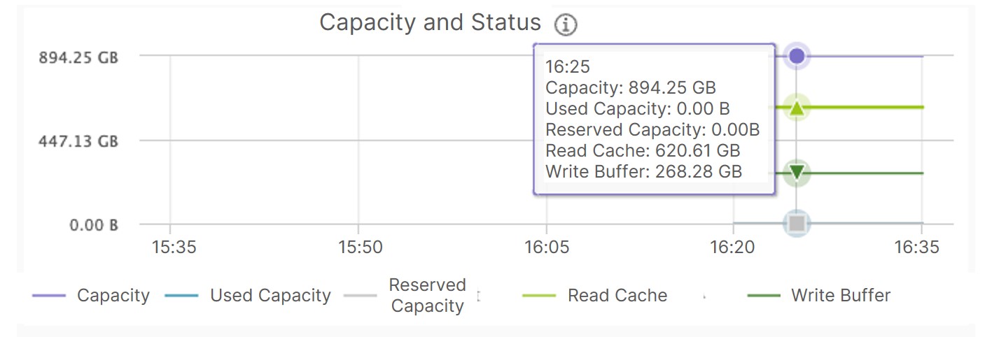
A single SSD disk has a capacity of 894.25 GB, with 620.61 GB as read cache and 268.28 GB as write cache. The read-to-write cache capacity ratio of 7:3 is in compliance with the description in VMware vSAN Design Guide.
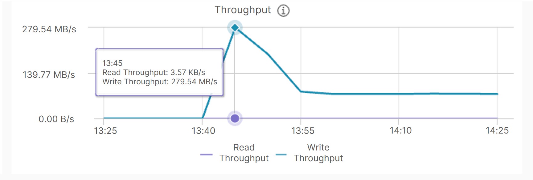
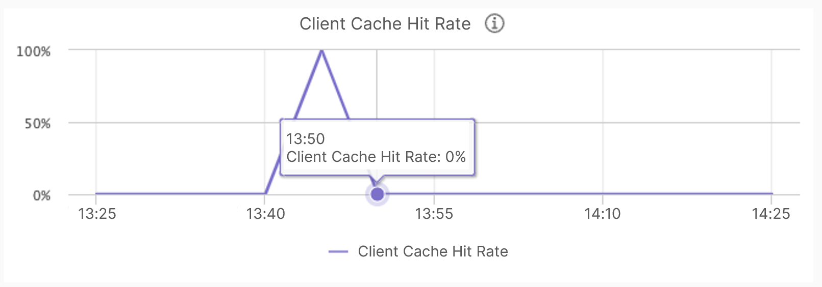
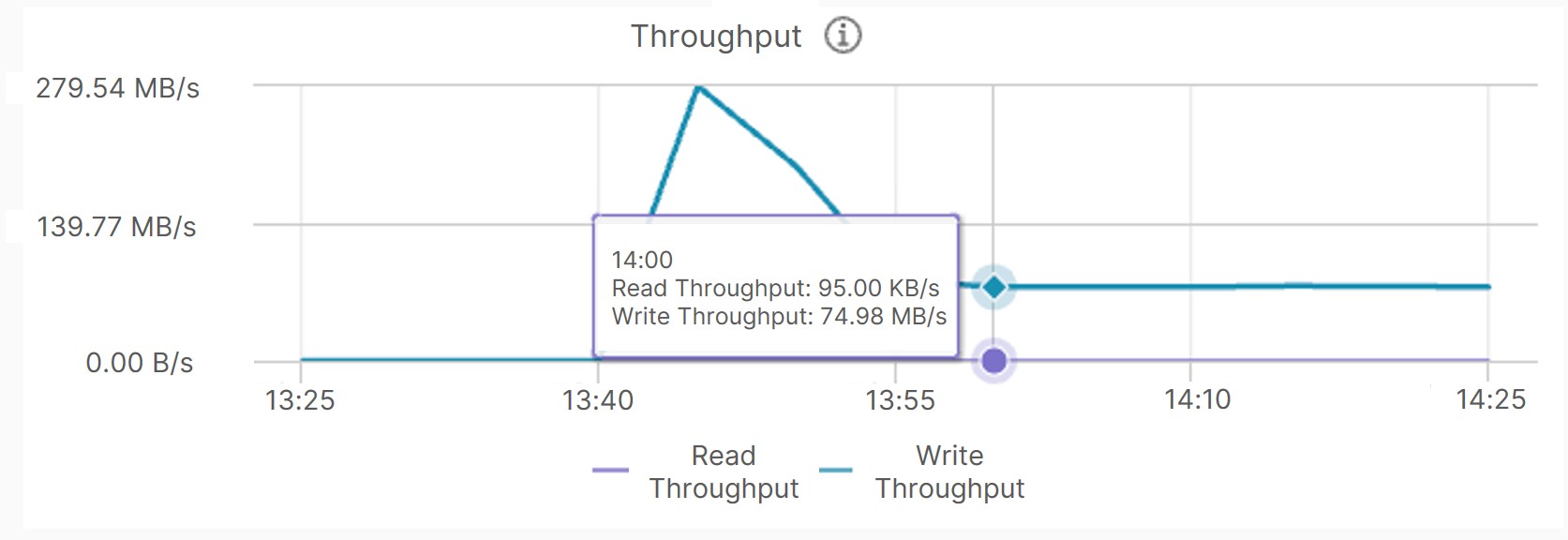
In the 256K sequential write test of 300 GB data, VM performance degraded from 280 MB/s to about 75 MB/s as a write cache breakdown occurred due to the insufficient cache space.
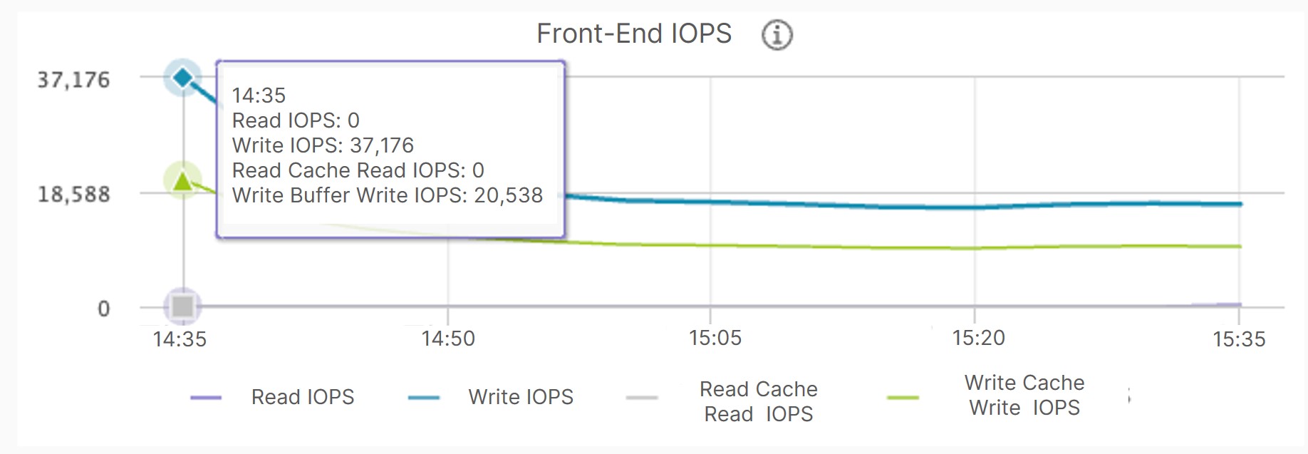
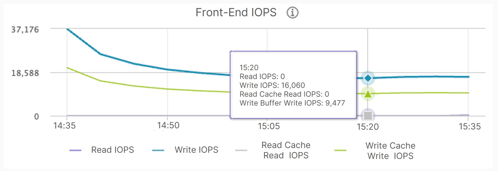
In the 4K random write test of 300 GB data, cache breakdown also resulted in a VM performance plunge, with IOPS dropping from 37,176 to 16,060.
As seen from above, vSAN employs separate read and write cache spaces, making it impossible to fully utilize the cache media in high-capacity data request scenarios, resulting in cache breakdown and storage performance degradation.
ZBS
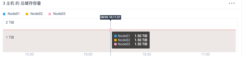
Each node has 1.5 TiB of available cache capacity (without individual read and write cache space). That is, the available cache capacity of two SSDs is about 900GB each.
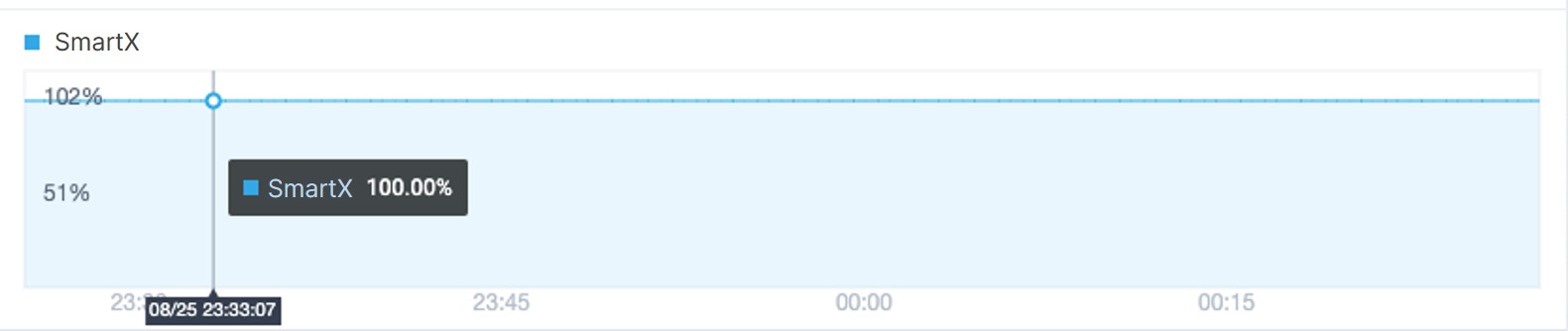
First, we used FIO to perform 256K sequential reads of 500 GB data in the test VM. The VM performance monitor indicated a stable VM performance with 100% cache hits. At this point, the written data is stored in Inactive.
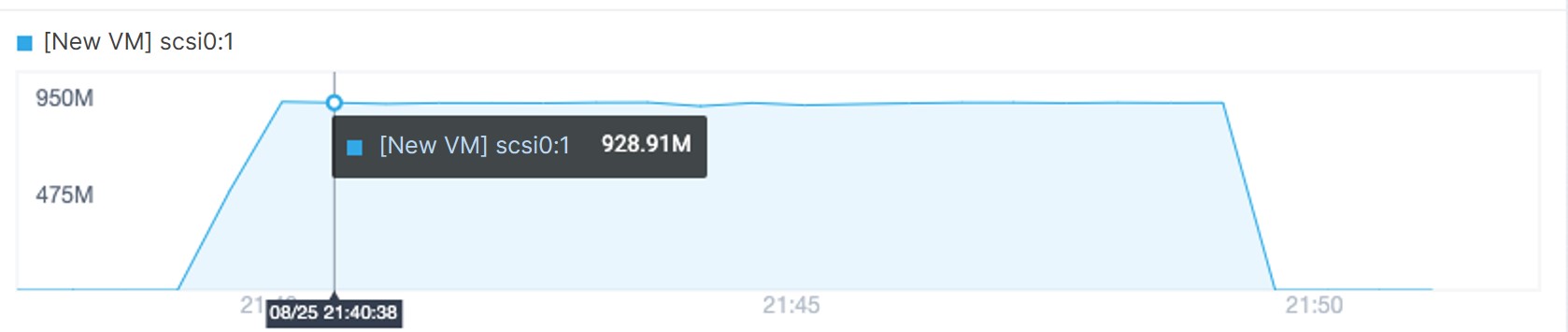

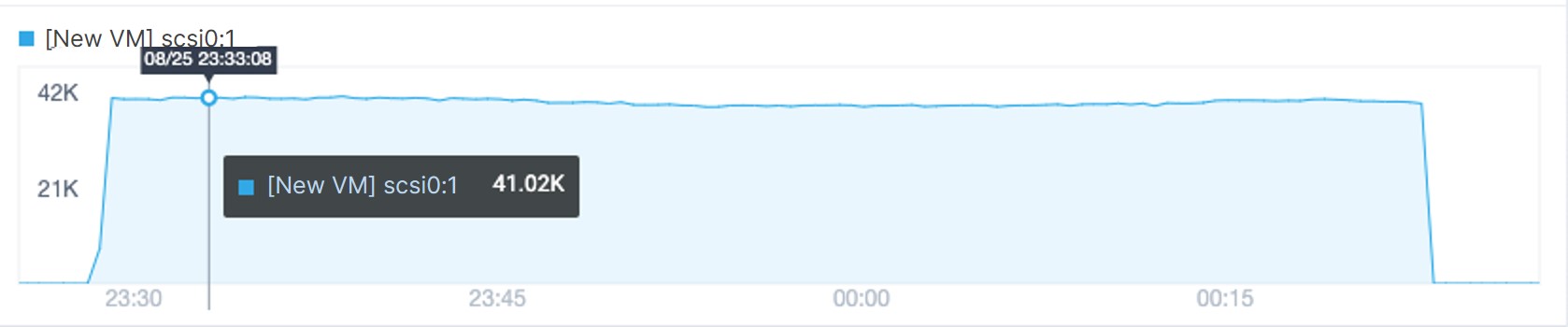
Next, we performed 4K random writes of 500 GB data to the VM. It was observed that the performance remained stable and no cache breakdown occurred.
Conclusion
From the above comparison, we can see that under the same data capacity and I/O read/write scenarios, ZBS’s unified caching mechanism effectively improves cache space utilization and prevents cache breakdown. Even under an outbreak of data access requests, there is no drop in VM performance, ensuring the stable operation of business.
You can check out more articles about SmartX HCI performance and product comparison on our blogs.
1 For disk groups in an all-flash configuration, the entire (100%) cache disk capacity can be used for write cache, leaving no more read cache.
References:
- VMware vSAN Design Guide
https://core.vmware.com/resource/vmware-vsan-design-guide - SMTX ZBS Block Storage Service & Technical White Paper
https://www.smartx.com/resource/doc/general-zbs-white-paper - Virtual SAN Read IO – cache / buffer / spindles
https://www.yellow-bricks.com/2014/01/15/virtual-san-read-io/ - An overview of VMware Virtual SAN caching algorithms
https://www.vmware.com/files/pdf/products/vsan/vmware-virtual-san-caching-whitepaper.pdf - Announcing vSAN 8
https://blogs.vmware.com/virtualblocks/2022/08/30/announcing-vsan-8-with-vsan-express-storage-architecture/